Coordinate Systems
Grids and Graticules - Definitions
GridA grid, or more specifically a Grid Reference System, is a means by which to reference locations on the Earth's surface using a two dimensional Cartesian coordinate system referenced to a map projection. A grid coordinate defining a location consists of and is written as an ordered pair of x and y values expressed in linear units. Standard grid reference systems used by NGA and DoD are the Universal Transverse Mercator (UTM) and the Military Grid Reference System (MGRS). Both of these grid reference systems use the meter as the unit of measure and define an easting (x) and northing (y) referenced to a series of transverse Mercator map projections with specific projection parameters.
Graticule A graticule, or more specifically a Geographic Reference System, is a means by which to reference locations on the Earth using a system of angles. A geographic coordinate defining a location is usually expressed in angular units of latitude and longitude. Latitude (φ - phi) is the angle between the equatorial plane and the straight line that passes through the point in question and the center of the reference shape (WGS84 ellipsoid). Longitude (Λ - lambda) is the angle east or west of the reference meridian (Greenwich Prime Meridian) to another meridian that passes through the point in question. The standard geographic reference system used by NGA and DoD are latitude and longitude expressed in sexagesimal (base 60) numbering system.
Global Area Reference System (GARS)
GARS is the standardized battlespace area reference system. It is based on lines of longitude (LONG) and latitude (LAT), and is used to provide an integrated common frame of reference for joint force situational awareness to facilitate air-to-ground coordination, deconfliction, integration, and synchronization. This area reference system provides a common language between components and simplifies communications. It is important to note that GARS is primarily designed as a battlespace management tool and not to be used for navigation or targeting.
Design
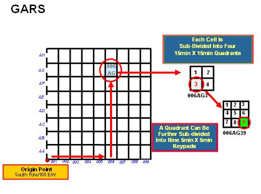
GARS divides a surface of the earth into 30-minute by 30-minute cells. Each cell is identified by a five-character designation (ex. 006AG). The first three characters designate a 30-minute wide longitudinal band. Beginning with the 180° meridian and proceeding eastward, the bands are numbered from 001 to 720, so that 180° E to 179° 30'W is band 001; 179° 30'W to 179° 00'W is band 002; and so on. The fourth and fifth characters designate a 30-minute wide latitudinal band. Beginning at the south pole and proceeding northward, the bands are lettered from AA to QZ (omitting I and O) so that 90° 00'S to 89° 30'S is band AA; 89° 30'S to 89° 00'S is band AB; and so on.
- Each 30-minute cell is divided into four 15-minute by 15-minute quadrants:
- The quadrants are numbered sequentially, from west to east, starting with the northernmost band. Specifically, the northwest quadrant is "1"; the northeast quadrant is "2"; the southwest quadrant is "3"; the southeast quadrant is "4".
- Each quadrant is identified by a six-character designation (ex. 006AG3). The first five characters comprise the 30-minute cell designation. The sixth character is the quadrant number.
- Each 15-minute quadrant is divided into nine 5-minute by 5-minute areas:
- The areas are numbered sequentially, from west to east, starting with the northernmost band. The graphical representation of a 15-minute quadrant with numbered 5-minute by 5-minute areas resembles a telephone keypad.
- Each 5-minute by 5-minute area, or keypad "key" is identified by a seven-character designation. The first six characters comprise the 15-minute quadrant designation. The seventh character is the keypad "key" number (ex.006AG39).
Military Grid Reference Systems (MGRS)
MGRS is an alpha-numeric system for expressing UTM/UPS coordinates. A single alpha-numeric value references a position that is unique for the entire earth. Using "15SWC8081751205" as an example, the components of MGRS values are as follows:
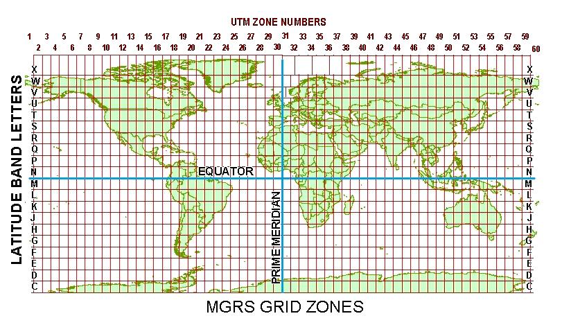
The first two characters represent the 6° wide UTM zone:- Leading zeros are included so that Zone 9 is "09".
- For polar areas outside the UTM area, these characters are omitted.
- Beginning at 80°S and preceding northward, the 20 bands are lettered C through X, omitting I and O.
- The bands are all 8° high except band X, which is 12° high.
- Outside the UTM area, and in leu of UTM zone numbers, A and B are used near the South Pole, Y and Z near the North Pole.
- The vertical UTM boundaries and horizontal latitude band boundaries form (generally) 6° X 8° Grid Zones. Hence, the first three letters of the MGRS value, e.g. "15S", are referred to as the Grid Zone Designator (GZD).
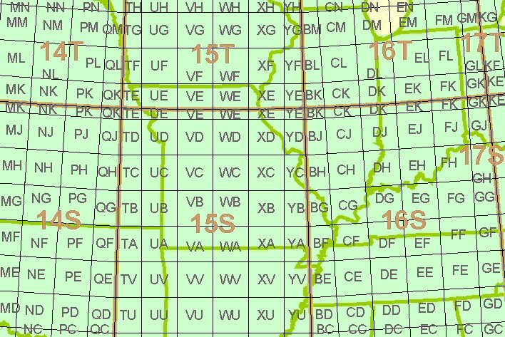
The fourth and fifth characters are a pair of letters identifying one of the 100,000-meter grid squares within the grid zone (or UPS area). See figure to the right.
- In the figure sample area, the Grid Zone Designators are shown in brown. The smaller gray letters are the 100,000-meter grid square identifiers. The example point "15SWC8081751205" is located in the square "WC" near the center of the figure.
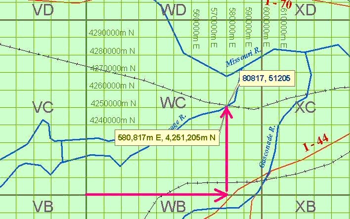
The remaining characters within the MGRS coordinate correspond to the UTM values starting with the numbers in the ten-thousands place in the Easting and Northing, and including more numbers depending on desired precision level. See figure to right. MGRS coordinates may be rounded to reflect lesser refinement. For example:
- 15SWC8081751205 is at 1-meter refinement
- 15SWC80825121 is at 10-meter refinement
- 15SWC808512 is at 100-meter refinement
- 15SWC8151 is at 1000-meter refinement
There are two lettering schemes for the 100,000-meter grid square identifiers. Generally, one scheme is used for WGS-84, and the other is used for older ellipsoids associated with the local datums:
- Example: 15SWC8081751205 is on WGS-84. When converted to NAD-27 datum, Clarke 1866 ellipsoid, its value is: 15SWN8083350993
- The 100,000-meter grid square "WC" for WGS-84 generally coincides with the grid square "WN" for Clarke 1866.
The magenta arrows show how MGRS Easting and Northing values are determined from within the 100,000-meter grid square. The MGRS value of this position is 15SWC8081751205. See figure to the right.
Universal Transverse Mercator (UTM)
UTM coordinates are based on a family of 120 Transverse Mercator map projections (two for each UTM zone, with one for each N/S hemisphere).
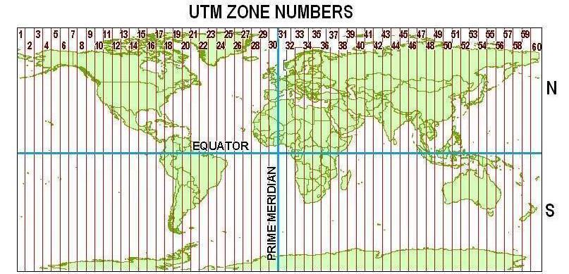
Numbering of zones begins at 180° and proceeds eastward:
- Zone 1 is from 180°W to 174°W
- Zone 2 is from 174°W to 168°W, and so on
Each zone also has a central meridian:
- Zone 1 central meridian is 177°W,
- Zone 2 central meridian is 171°W, and so on
Design
UTM divides the earth into 60 zones, each 6° wide in longitude (with the exception of a few non-standard-width zones for Svalbard and southwest Norway).
UTM is limited to the area between 84°N and 80°S. Beyond that, Universal Polar Stereographic (UPS) coordinates are used. See section on UPS.
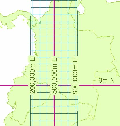
- The X value, called the Easting, has a value of 500,000m at the central meridian of each zone. See figure on left.
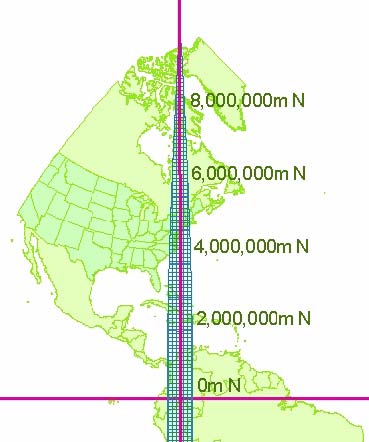
- The Y value, called the Northing, has a value of 0m at the equator for the northern hemisphere and 10,000,000m at the equator for the southern hemisphere. See figure on right.
Positioning
UTM divides the earth into 60 zones, each 6° wide in longitude (with the exception of a few non-standard-width zones for Svalbard and southwest Norway).
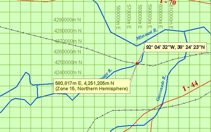
- In the UTM system, positions are expressed as Easting / Northing, e.g. "580817mE, 4251205mN". In some cases, the letters are left off, e.g. "580817 4251205".
- If positions occur near UTM zone junctions, the UTM zone may also be specified, e.g. "580817mE, 4251205mN, Zone 15".
- Since the above expresses two possible positions on the earth, the hemisphere may also be specified, e.g. "580817mE, 4251205mN, Zone 15, Northern Hemisphere" (Figure 4).
- Many systems abbreviate the above, representing the hemisphere as a single letter, "N" for northern hemisphere, and "S" for southern hemisphere, e.g. "15N 580817 4251205".
Universal Polar Stereographic (UPS)
Design
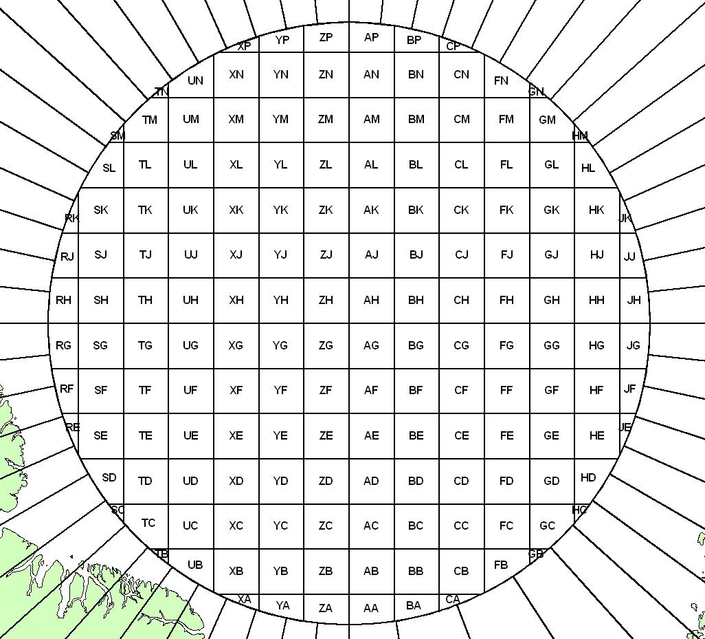
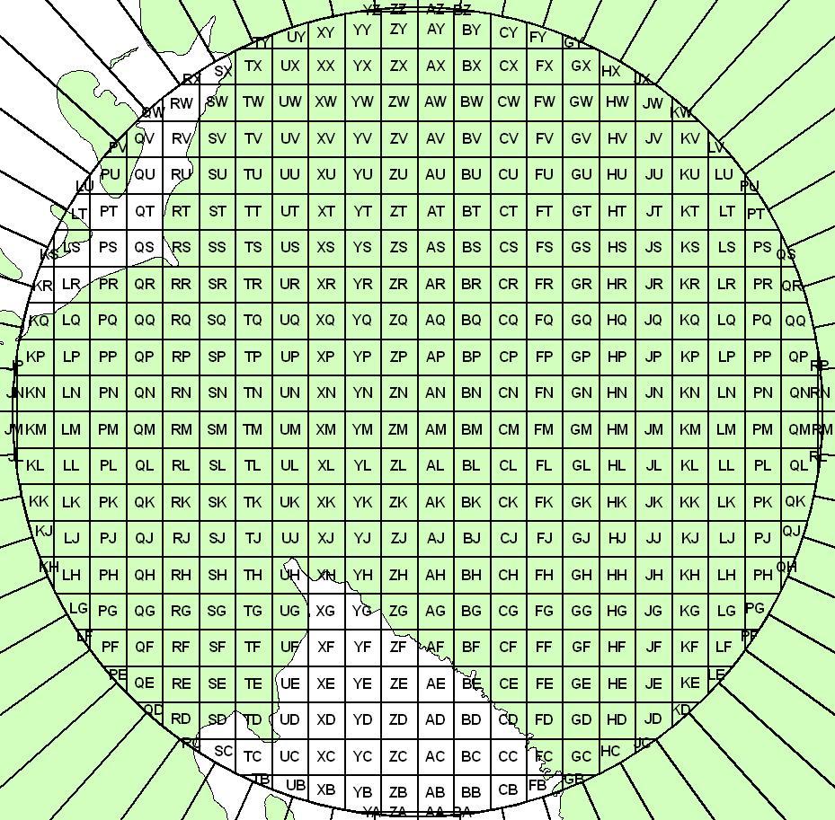
The Universal Polar Stereographic (UPS) Systems coordinates are based on a family of two Polar Stereographic map projections, one for each pole.
- The origin of the UPS coordinate system is at the poles, where X=2,000,000m and Y=2,000,000m.
- The X-axis lies along the meridians 90°E and 90°W:
- Moving from the pole (north or south), X-values (Eastings) increase along the 90°E meridian
- The Y-axis lies along the meridians 0° and 180°:
- Moving from the North Pole, Y-values (Northings) increase along the 180° meridian.
- Moving from the South Pole, Y-values (Northings) increase along the 0° meridian.
UPS North, 100km MGRS Letters: top image
UPS South, 100km MGRS Letters: bottom image
Latitude/longitude
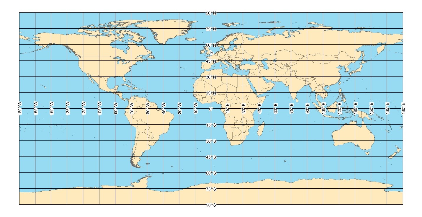
Latitude/longitude is a geographic reference system used to define positions on the Earth. It consists of angles of latitude that are measured from the center of the Earth and are referenced starting at the Equator, which is assigned 0°. Moving north and south of the Equator, latitudes increase in number from 0° to 90° at the two poles. Angles of longitude are also measured from the center of the Earth and are referenced starting at the Prime Meridian, which is assigned 0°. Moving east and west of the Prime Meridian, longitudes increase in number from 0° to 180°. A Latitude/Longitude coordinate must include Latitude and Longitude parts in conjunction to define a location.
Following the sexagesimal, base 60, system, degrees can be subdivided into 60 minutes, and minutes can be subdivided into 60 seconds, for the purpose of increased precision level. This can result in several formats, such as degrees-minutes-seconds, degrees-decimal minutes, and decimal degrees. The more digits included in the coordinate string, the higher the precision level.
To indicate hemisphere, the abbreviations for north, south, east, and west (NSEW) are commonly used. An alternate manner to indicate hemisphere is to use the minus sign for latitudes in the southern hemisphere and longitudes in the eastern hemisphere. The plus sign is usually not written and indicates northern or western hemisphere.
World Geographic Reference (GEOREF) System
The World Geographic Reference System (GEOREF) is an area reference system used for interservice reporting for air defense and strategic air operations. It provides a method of expressing position in a form suitable for reporting and plotting and may be applied to any map or chart graduated in latitude and longitude. Click here for a detailed description of the GEOREF system.
United States National Grid (USNG)
The USNG is a coordinate reference system used for locating points and areas on the surface of the Earth and is functionally equivalent to the Military Grid Reference System (MGRS). The main difference between the two systems is in the method for specifying the datum. In MGRS, an alternate lettering scheme (Old Letters) is used for the 100,000-meter Square Identifier when the position is referenced to an older datum. The USNG does not use the alternate lettering scheme, but simply specifies the datum after the position reference. For example, a position on the NAD27 datum is reported in the two systems as follows:
- MGRS: 15SWN8083350993
- USNG: 15SWC8083350993 (NAD27)
Specialty Grids
The NGA Office of Geomatics maintains the following specialty grids:
- World Aeronautical Chart (WAC): A charting system bounded by parallels and meridians usually at 4° increments chosen to create areas approximately 240nm x 360nm.
- Air Target Chart (ATC): A subdivision of the World Aeronautical Chart (WAC) charting system. There are 25 ATCs within each WAC.
- World Target Mosaic (WTM): A subdivision of the Air Target Chart (ATC), which is in turn a subdivision of the World Aeronautical Chart (WAC) charting system. A WTM usually covers an area 12nm x 18nm and is the basic collection unit for Broad Area Search (BAS) imagery. There are 16 WTMs within each ATC.
- WAC Target Mosaic Subcell (WTMS): A subdivision of the World Target Mosaic (WTM), which is a subdivision of the Air Target Chart (ATC), which is in turn a subdivision of the World Aeronautical Chart (WAC) charting system. There are 24 WTMS within a WTM.
- Rapid Worldwide Area Collection 9x9 (RWAC 9x9): A subcell of the World Aeronautical Chart (WAC) charting system defined as a WAC is divided into 27 rows x 40 columns. A system of RWAC 9 x 9 areas is a target reference and planning tool, which uses a ten-digit identifier that uniquely identifies a four-corner geographic area configured as a 9nm x 9nm box.
- Rapid Worldwide Area Collection 3x3 (RWAC 3x3): A subcell of the World Aeronautical Chart (WAC) charting system defined as a RWAC 9x9 divided into 9 parts (3 rows x 3 columns). It is the basic unit of area search target reporting. A target reference and planning tool, which uses a ten-digit identifier that uniquely identifies a four-corner geographic area configured as a 3nm x 3nm box.
Geodetic Research and Packages
Geodetic ResearchGeodetic Research is the attempt to discover missing geodetic metadata in regards to coordinate data or maps to give them added spatial context. In most cases, if there is missing geodetic metadata, geodetic research is the process by which geodetic scientists use tools such as GIS, geographic translators, calculations, library of geodetic information and open source to learn likely geodetic reference ellipsoids/datums, grid/map projection parameters, a means by which to convert/translate the information to an NGA geodetic standard and a way to properly display the information and verify its location.
Geodetic PackageA Geodetic Package is a collection of geodetic information for a specific NGA standard map product to ensure that it has the timely and necessary information to properly place reference system lines, proper reference system labels and magnetic information. Geodetic Packages are required of all NGA standard map products and the software program to create them is GEOPAK.
GIS Grid Layers
| GRID | LINK | DESCRIPTION |
|---|---|---|
| UTM | UTM Zones |
UTM Zone 1-60, hemispheres north and south polygon shapefiles |
| UTM | UTM 10km Polylines |
UTM lines at 10km spacing in continent-size shapefiles |
| UTM | UTM 1km Polylines |
UTM lines at 1km spacing in 6°x8° shapefiles |
| GARS | GARS Polygons |
GARS polygons at 30', 15' & 5' granularity in 20°x20° areas as shapefiles & drawing files |
| MGRS |
MGRS 1km Polygons
PKI certs required
|
MGRS polygons at 1km spacing in 6°x8° shapefiles |
| MGRS | MGRS 100km Polygons |
MGRS 100km Square Identifier polygons in 6°x8° shapefiles |
| MGRS | MGRS 100km Polygons - Worldwide |
MGRS 100km Square Identifier polygons - worldwide shapefile |
| MGRS | MGRS Grid Zone Designator Polygons |
MGRS Grid Zone Designator (6°x8°) polygons |
| MGRS | MGRS 100km Square Identifier Polygons UPS North |
MGRS 100km Square Identifier polygons UPS north |
| MGRS | MGRS 100km Square Identifier Polygons UPS South |
MGRS 100km Square Identifier polygons UPS south |
Gold Data v6.3 Testing For Datum Transformations and Coordinate Conversion Software
While GEOTRANS is the NGA recommended and supported software package for Datum Transformations and Coordinate Conversions, there are occasions when something else is requested or proposed, and needs to be tested. For such occasions, software developers are invited to download the following ZIP collection of test files. These are files created by NGA geodesists working independently of GEOTRANS. The files are simulated data (not measurements) and provide a higher accuracy standard for software performance than does GEOTRANS as of 3/25/2009 for the algorithms treated. Also, in some cases, they allow input values that GEOTRANS does not. Therefore, if developers have not carefully defined the domain of valid inputs and implemented the corresponding input checking, these tests are likely to reveal the lack thereof. The files "Instructions.doc" and "Release_Notes.doc", found in the ZIP, contain further information. This is an ongoing project, and more tests will be added in later releases. Comments are welcome at the e-mail address below.
COORDINATE SYSTEMS APPS PKI certs required
Geodetic Packages (GEOPAK)
A geodetic package is a collection of geodetic metadata used for grid, graticule and magnetic verification for all NGA standard map products. The software to create a geodetic package is GEOPAK and is available at https://earth-info.nga.mil/geopak.
Tiled Image Converter 2.1
The Tiled Image Converter is a GUI based program built by the Naval Research Laboratory that is capable of converting entire pyramids of raster tiles away from the input map projections into one of the output map projections. The input map projections are web Mercator (also known as EPSG::3857), WGS 84 Plate Carree (also known as EPSG::4326), and Mercator. The output map projections are Mercator and Plate Carree. The software is available at the NGA GEOINT APP Store.
Services PKI certs required
Allows visualization via the IC Portal or ArcGIS desktop (download). After selecting the link below, additional viewing options may be available by following the link under the "Map Contents" heading.
| LINK | DESCRIPTION |
|---|---|
Air Target Chart (ATC) |
Air Target Chart (ATC) is a subdivision of the World Aeronautical Chart (WAC). There are 25 ATC per WAC. ATC is visible at scale of 1:9,000,000 and larger |
Global Area Reference System (GARS) |
GARS is the standardized battlespace area reference system across DoD which will impact the entire spectrum of battlespace deconfliction. |
Latitude/Longitude Graticule |
Latitude/Longitude is a geographic coordinate measurement used in mapping, charting, and geodesy to reference positions on the Earth. |
Military Grid Reference System (MGRS) |
MGRS is an alpha-numeric system for expressing UTM/UPS. A single alpha-numeric value references a position that is unique for the entire earth. |
Rapid Worldwide Area Collection (RWAC) |
Rapid Worldwide Area Collection (RWAC) is a ten digit identifier that uniquely identifies a four-corner geographic coordinate box configured either as a 3x3nm or 9x9nm box. RWAC is visible at scale of 1:1,000,000 and larger |
World Aeronautical Chart (WAC) |
World Aeronautical Chart (WAC) is a chart system overlaying the Earth's surface bounded by pairs of parallels at 4 degree increments and meridians at integral degree boundaries chosen to give approximately 360 nautical mile regions. |
World Target Mosaic (WTM) |
World Target Mosaic (WTM), also referred to as World Aeronatical Chart (WAC) Target Mosiac, is a subdivision of the Air Target Chart (ATC) and is the basic collection unit for the Broad Area Search (BAS) imagery. There are 16 WTM per ATC. WTM is visible at scale of 1:2,000,000 and larger |